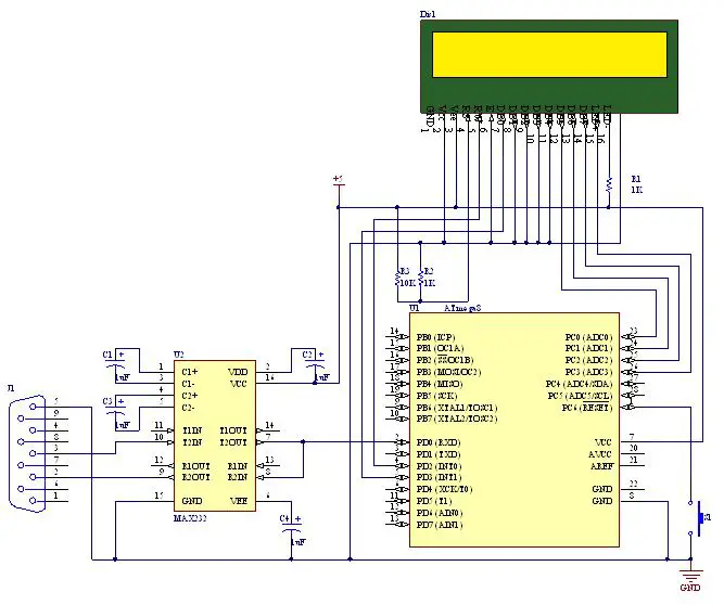
Hello everyone, I am learning how to use header files with UART on ATmega8. I have two problems: First one for some reason the registers like identifier “UBRR0L” is undefined and the rest of them. And the second one is it does not include the header file. I dont know if these two problem are related. I have tried my best to resolve using examples but to no end. Here are the screenshots. Also check: UART communication between two ATmega controllers In this project ATMEGA8 acts as a TRANSMITTER and ARDUINO UNO acts as a RECECIVER. In serial communication we will send data BIT BY BIT, until a BYTE of data is transferred completely.
So here we are with the AVR communication protocols series, starting with the most basic ones, UART and USART! We will move on to SPI and TWI (I2C) later. Some images used in this tutorial are taken directly from (and are a courtesy of) the AVR datasheets for ATMega8 and ATMega16/32 microcontrollers. Programming software. So it was common to throw a pre-programmed ethernet “coprocessor” on it and just bit/byte bang as you would with a UART. Arduino vs avr atmega8 its comparing.
If You come there from internet search i assume You already know what is PWM and where it can be used, so in this post I’ll only explain how to use 8 bit timer in Atmega8 to generate PWM signal and control frequency, polarity and duty cycle.
PWM can be generated from 16-bit Timer/Counter1 or 8-bit Timer/Counter2 but this time I’ll only explain 8-bit Timer/Counter2Fast PWM Mode.

In this picture from Atmega8 documentation Fast PWM mode is explained. Counter(8bit) counts from 0x00 to 0xFF and restarts from 0x00. In not inverting mode OC2 is cleared when counter match value in OCR2 register and set at 0x00. In inverting mode OC2 is set when counter match value in OCR2 register and cleared at 0x00.
Atmega8 Uart Program In C
From this all turns out that PWM duty cycle depends on OCR2 register. In not inverting mode duty cycle = OCR2/256*100% and it’s 50% if OCR2 is 0x80(middle between 0x00 – 0xFF).
Atmega8 Uart Program Download
In every PWM period counter must count 256 steps, so frequency of signal is 256 times lower than counter clock from prescaler. PWM frequency = Atmega clock frequency/timer prescaler(1,8,32,64,128,256)/256. With 4 MHz crystal maximum(without prescaler) PWM frequency is 15 625Hz.
Register setup
For example 15 625 Hz, 50 % duty cycle, non-inverting mode PWM signal generation.
1. OCR2=0x80(128); As mentioned before duty cycle = OCR2/256*100%
2. TCCR2=0x69;
3. DDRB=0x08; PWM signal is outputted by toggling level of PORTB pin 3.
DDRB sets it as output.
All together:

#include <iom8.h>
int main( void )
{
DDRB=0x08;
OCR2=0x80;
TCCR2=0x69;
while (1) {};
}
Result:
~10% duty cycle, 61 Hz.
#include <iom8.h>
int main( void )
{
DDRB=0x08;
OCR2=0x1A; // 256/10=25,6 26 in hex = 1A;
TCCR2=0x6E; // 256 prescaler
while (1) {};
}
Result:

And there is demo program and *.hex file for PWM demo seen in video.

Atmega8 Uart Programme
Atmega8 PWM demo program (1.8 KiB, 8,281 hits)